In this tutorial we will learn to control the Vertex Delta with OctoPrint, installing and connecting the Raspberry Pi 3B+ and camera module with night vision (optional) onto your Delta, with the specially designed enclosures. In this way, you can keep an eye on your 3D prints from over the web! You can find all the information on Octoprint`s open-source software on their website: https://octoprint.org/.
1. Materials


Ingredients:
- 3D printed RPI case
- 3D printed mainboard cover for vertex Delta
- 3D printed camera case (optional)
- camera module with 2 IR lights for Raspberry Pi (VMP404) (optional)
- Raspberry Pi 3 model B+ – (or 4!)
- DC-DC adjustable voltage step down module (VPM 4040)
- USB A – B cable
- PC or Laptop connected to the internet
- 4x Jumper wires (male to female) or normal wires (~15cm)
- 2pin header (optional)
Tools:
- PC or Laptop connected to the internet
- one assembled Vertex Delta
- hex keys
- solder iron
- cutting pliers
- wire stripper
2. Setting up Octoprint on your Raspberry Pi
The people from Octoprint have written a clear guide on how to download and install Octoprint on your Raspberry Pi. Follow the instructions over there: https://octoprint.org/download/
3. Printing the enclosures
Download and 3D print the files here, for an easy and clean installation of your Raspberry Pi 3B+ and camera onto your Vertex Delta


4. Assembling the electronics
After Octoprint is installed succesfully onto your Raspberry Pi and you 3D printed the files, we can now mount the electronics onto your Delta.
1. Switch off your Delta, and unplug the power chord. After that remove the printbed


2. Unscrew the 6 hex bolts from the aluminium bed plate ring, circled in red (do not lose the bolts).


3. Unplug the 3 piezo connectors from the main board, circled in red. Then remove the aluminium bed plate ring.


4. Unplug all connectors from the main board (circled in red). After that, unscrew the 3 hex bolts that hold the mainboard cover in place. Again, you do not want to lose these bolts…. For real :) .


5. Remove the mainboard cover. unplug the cables from power switch (circled in red), then remove the mainboard itself.


6. Solder 2x male header onto the mainboard`s VIN+ and GND (SK2 pin row, circled in red). If you don`t have headers, you can solder wires directly onto the mainboard.


7.While we are at our solder station…. Solder the 4 jumper wires to the DC-DC step down converter (like in the picture below).


8. Now we can mount the mainboard back in place. Reconnect the power switch to the main board


9. Place the mainboard, and the 3D printed mainboard cover back in place. Fasten it with the 3 hex bolts.


10. Reconnect all connectors to the mainboard.


11. Before we can mount the ALU plate ring back in place, position the USB A to B cable between the ALU ring and the Delta`s base, like in the picture below. Make sure the B side of the cable is on the outside, on the power side.


12. Remount the ALU plate ring with the 6 hex bolts (circled in red). Then reconnect the piezo connectors to the mainboard (circled in yellow).


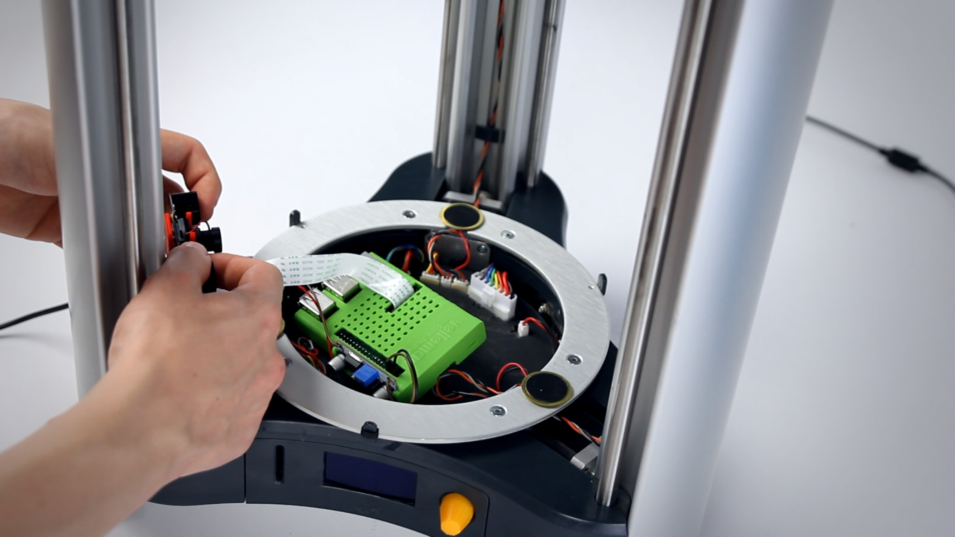
13. Slide your Raspberry Pi in the 3D printed enclosure.


14. Clip the converter in the side of the RPI case.


ATTENTION
Connect the IN+ & IN- from the DC-DC step down converter to The VIN+ & GND from the delta`s mainboard (or another 15V source). Measure the output voltage on the OUT + & OUT – of the Step down converter with a multimeter, This should be ~5v. You can adjust the voltage by turning the wheel of the potmeter (see picture below)


15. Connect the OUT+ form the step down to the RPI`s 5V, and the OUT – to the RPI`s GND (See connection scheme)


16. (OPTIONAL) Slide the Camera in the 3d printed enclosure, then connect the ribbon cable to the Raspberry`s camera connector.


17. Place the raspberry on the delta`s mainboard cover (beneath the printbed) and clip the camera on the vertical slider rod (at the bottom)


18. connect the USB cable (A side) to a USB port of the Raspberry Pi


19. Connect the IN+ & IN- of the step down converter to the header on the mainboard we soldered earilier.


20. put the print bed back in place, and connect the other side of the USB cable (B side) to the USB B connector of the delta.


21. Connect the power cable, and switch on the Delta

5. Setting up OctroPrint for your Vertex Delta
- Open up a web browser on your pc, and surf to
http://octopi.localorhttp://<your pi's ip address>. For troubleshooting please visit: https://github.com/guysoft/OctoPi


2. Go to the OctoPrint settings tab, and add baudrate 500 000 in the additional baud rates field. Then select baudrate 500 000 at the drop down menu.


3. Click connect, to connect to your Raspberry Pi


4. (Optional) under the control tab, you can see view the camera stream.


DONE! Now start printing. Slice the 3D objects you want to print with the normal cura slicer on your PC. Then select the Gcode from OctoPrint`s web page.